FEA Analysis on Rocketdyne F-1 Rocket Engine - Flanged Nozzle Bolt
14 Dec 2020Overview
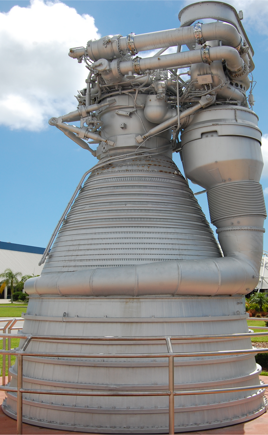 Rocketdyne F-1 Rocket Engine - First Stage
The goal of this research is to analyze the bolted flange joint that connect the mid and lower parts of the F1 engine nozzle. The image below shows the simplified corresponding nozzle model in ANSYS (upper nozzle is excluded in this analysis). Analysis will be done using a non-linear finite element model in ANSYS to assess the margin of safety of the flange bolts and determine the gaps that develop between the jointed parts when the assembly is loaded.
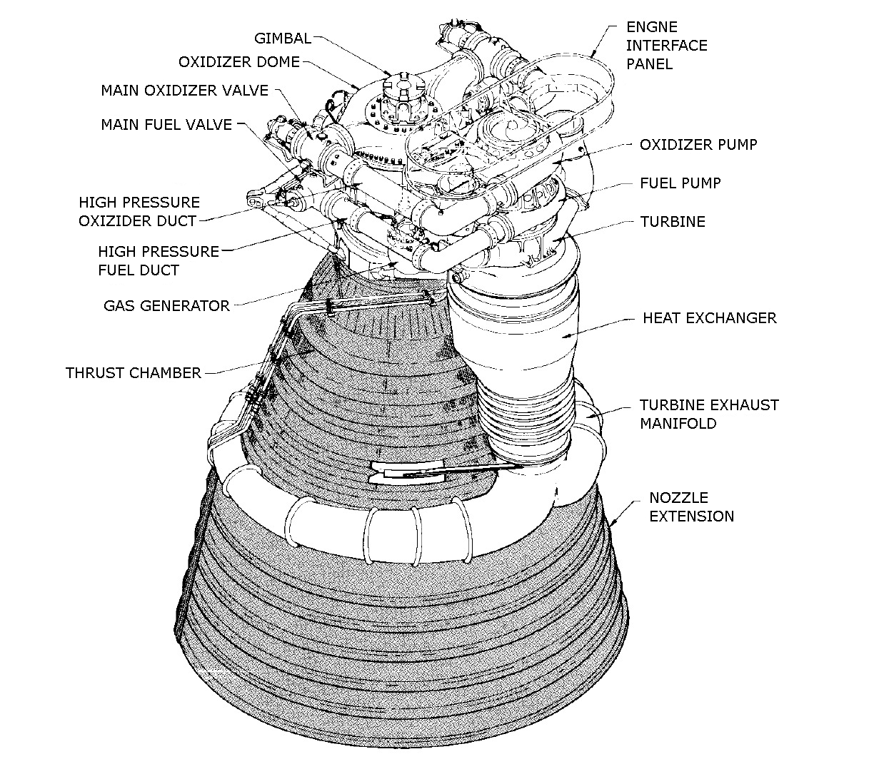 Saturn F1 Engine Diagram
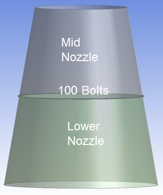 Overall Simplified ANSYS Model
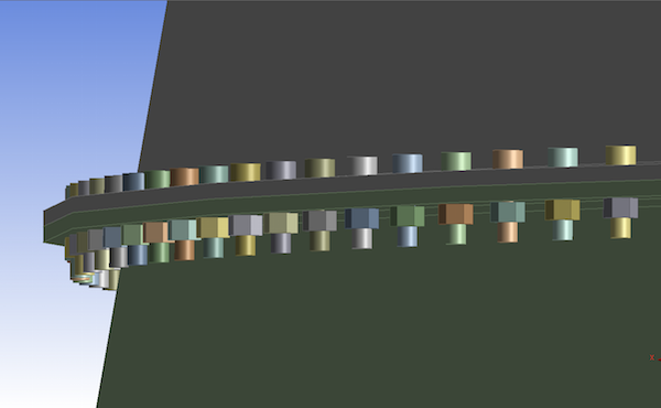 200 Bolts Securing Middle and Lower Part of the Nozzle
Below are the material properties that are going to be used for this analysis.
| Parts | Material | Young’s Modulus (psi) | Poisson’s Ratio | Coefficient of Thermal Expansion (per deg. F) |
|---|---|---|---|---|
| Nozzle | 300 Series Stainless Steel | 29000000 | 0.27 | 0.00001 |
| Bolt and Nut | A-286 Steel | 29000000 | 0.31 | 0.0000095 |
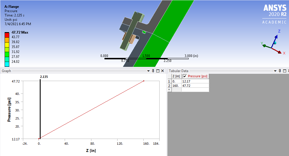
The pressure due to the exhaust gas in the nozzle is calculated using 1D gas dynamics. It is assumed to vary linearly along the nozzle axis. The pressure at the exit (z=0) is 12.17 psi and the pressure at the entrance to the mid-nozzle is 47.72 psi.
The regeneration channels are omitted in the model. In exchange, a free body diagram is used to deduce the equivalent forces on the mid nozzle and lower nozzle (the upper nozzle is not modeled here). This force pair is modeled as two separate forces, each of 1000 lbf. The gas temperature is 700 F which causes thermal strain. The bolt is assumed to be pre-loaded to 50% of its breaking strength.
Essential Boundary Conditions & Governing Equations
Boundary conditions and assumptions:
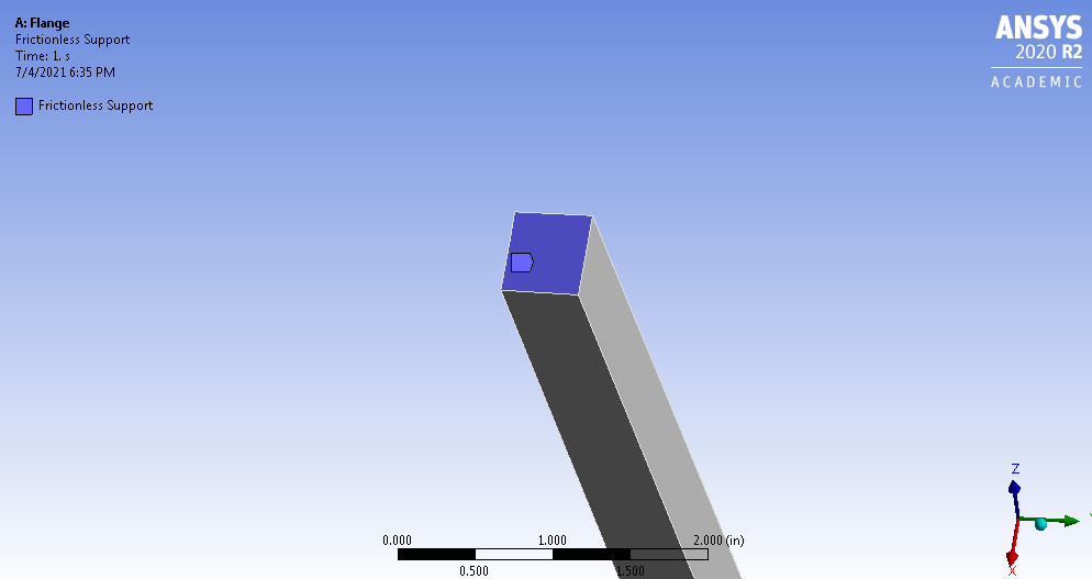
- Frictionless support at the top surface of mid nozzle
- Normal displacement = 0
- Tangential traction (Shear) = 0
- Pressure due to propellant
- Obey 1D gas dynamics
- Varies in axial direction (z-axis)
- Force from regeneration channels
- Pulls apart the mid and lower nozzles
Governing equations are as follows:
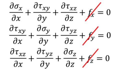 Differential Equations of Equilibrium
 Strain-Displacement Relations
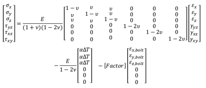 Constitutive Matrix Model
Initial Calculation/Prediction
Axial Reaction of Thrust
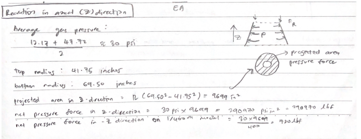
Based on the projected area of pressure in the mid & lower part of nozzle (shaded concentric circle), we can calculate the net force in the negative z-direction. That would be the net reaction force for the whole geometry, assuming that the top mid part of the nozzle is fixed to wall/support.
The calculated projected area in the mid & lower part of nozzle is to be 9,699 \(in^2\), thus the net pressure force based on the average gas pressure at the entrance of mid nozzle and at the exit of lower nozzle is 290,970 \(lbf\).
Our model is scale to 1:400, so the net pressure force of 1/400th of the model is 727 \(lbf\).
Hoop Stress on Nozzle

We can estimate the hoop stress or the stress in the circumferential direction of the nozzle. Based on the pressure vessel theory, we can find the hoop stress is given as follow:
\[\begin{equation}\sigma_{\theta} = \frac{Pr}{t}\end{equation}\]where \(P\) is the pressure, \(r\) is the radius, and \(t\) is the wall thickness. Plugging in all the value and we’ll get estimated hoop stress for the nozzle.
\[\begin{equation}\sigma_{\theta} = \frac{12.17 psi * 69.5 in}{0.5 in} = 1692 in\label{hoop-stress}\end{equation}\]Thermal Strain of the Nozzle

The estimated deformation due to thermal stress can be calculated using the following thermal strain formula as shown below:
\[\begin{eqnarray}\frac{\delta l}{L} = \alpha\Delta T\\\frac{\delta l}{160 in} = (1e^{-5})(700 ℉ - 70 ℉) = 1.008 in\label{thermal_strain}\end{eqnarray}\]Bolt Preload Deformation
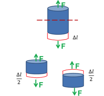
The bolt is pre-loaded with 50% of it’s ultimate tensile strength which is 9280\(lb\), so the load applied is 4640\(lb\), and on each side is 2320\(lb\).
\[\begin{eqnarray}\Delta l = \frac{FL}{EA}\\\Delta l = \frac{2320lbf * 0.5 in}{(2.9*10^{7}psi)*(3.8*10^{-2}in^2)} = 0.001 in\end{eqnarray}\]Meshing
Meshes were set up using 2 different body sizing; 0.3 inches element size for the middle and lower part of the nozzle, and 0.075 inches element size for the bolt & nuts. Statistics of the following mesh setup are as follow:
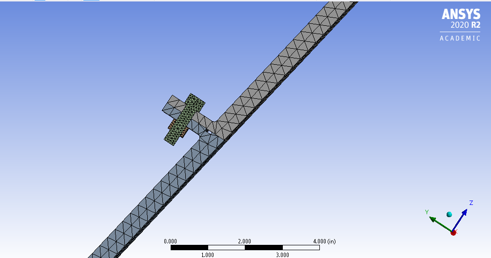 Tetrahedron Meshes Setup
 Meshes Statistics
The number of nodes exceed the maximum number of nodes for ANSYS student, so we need to reduce the number using different meshes method; Hex dominant. Below are the meshes generated and it’s statistics:
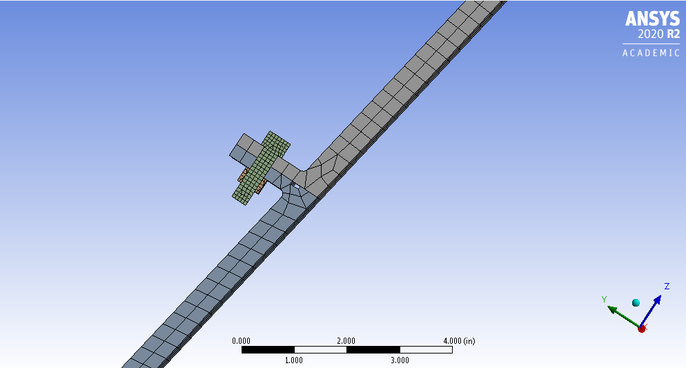 Hex Dominant Meshes Setup
 Meshes Statistics
Boundary Conditions Setup
Applying Thermal Strain
Thermal strain was applied to all the part of the nozzle including the bolt and nuts using time steps series as follows:
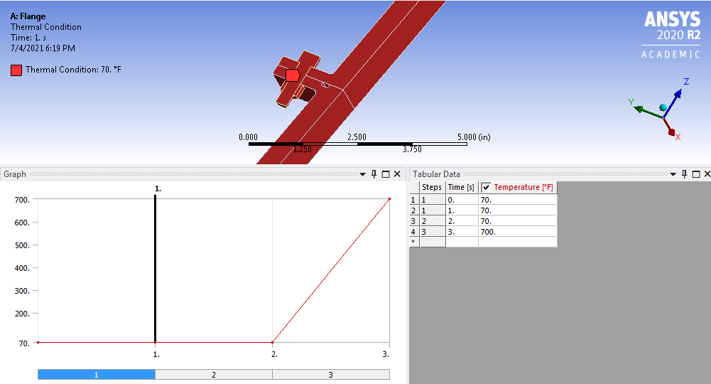
Applying Bolt Preload
Load bolt pretension was applied to the surface of the bolt thread as follows:
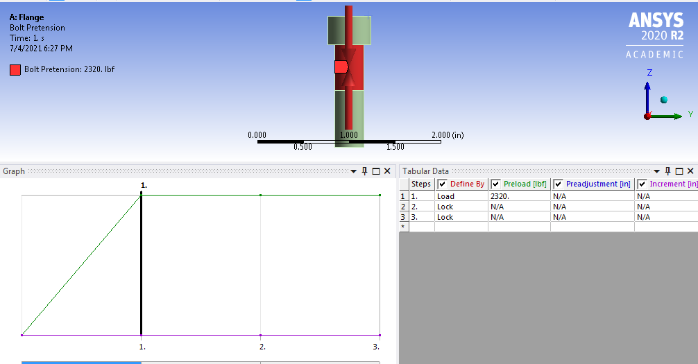
Applying Boundary Conditions
Frictionless support was added to the top of middle nozzle.
Applying Pressure Load
Pressure load due to expansion of hot gas due to combustion needs to be applied to surfaces that are exposed to the hot gas including the regeneration channel near to the bolt and nuts.
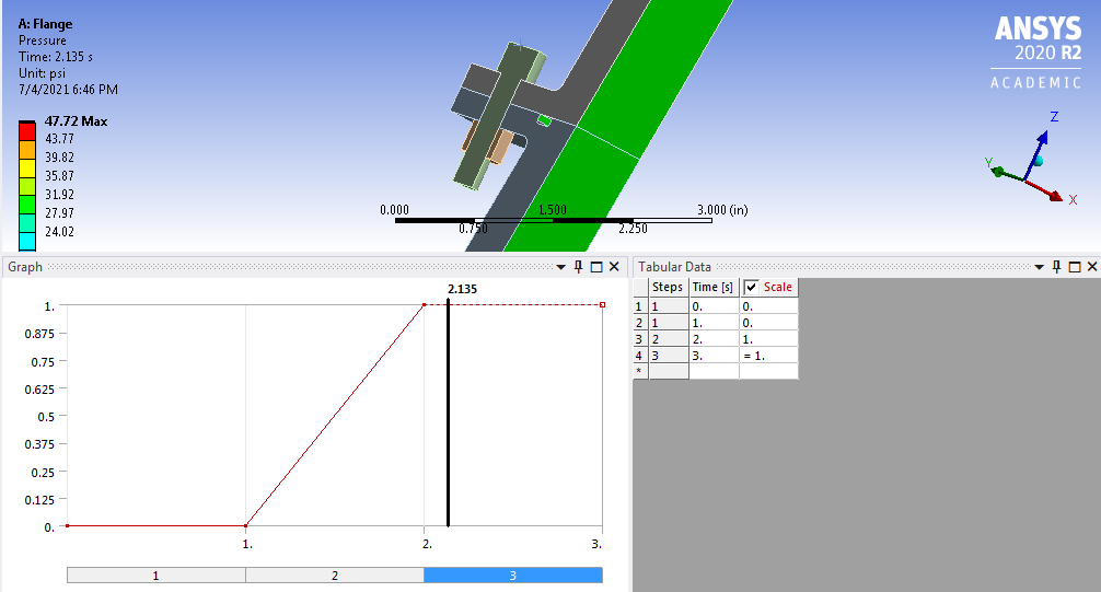 Pressure Load Time Step
Applying Load due to Regeneration Channel
Forces from the regeneration channel can be simulated by applying load in z-direction at the surface between the middle and lower part of the nozzle.
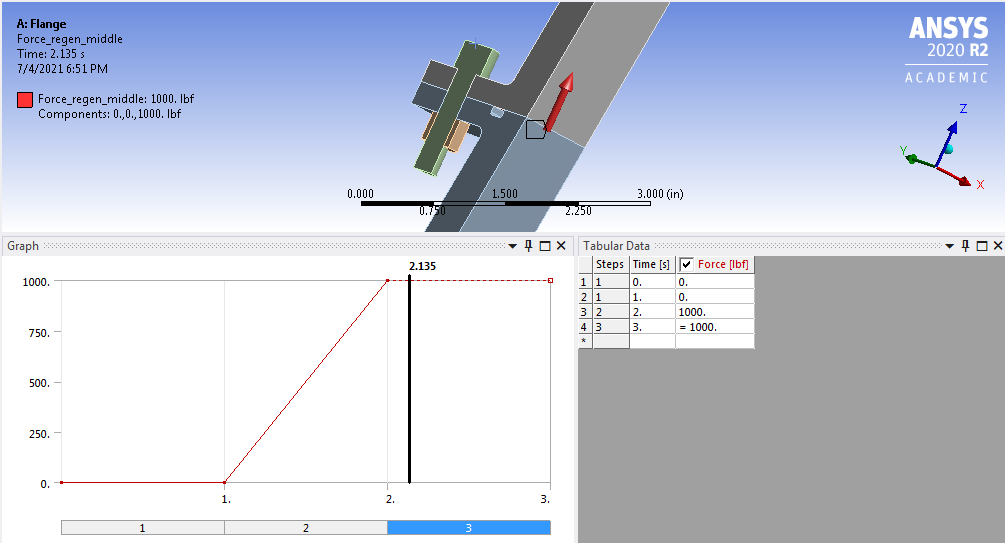 Simulated Regeneration Channel Load at Middle Nozzle
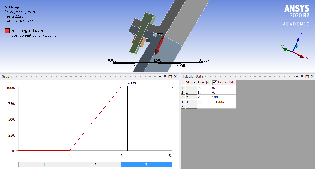 Simulated Regeneration Channel Load at Lower Nozzle
Contact Surfaces
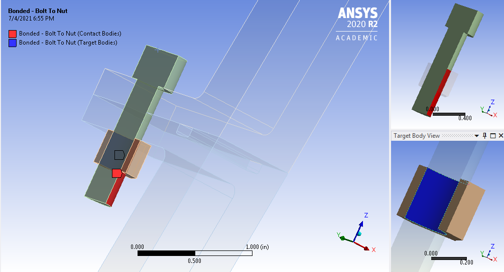 Bolt to Nut
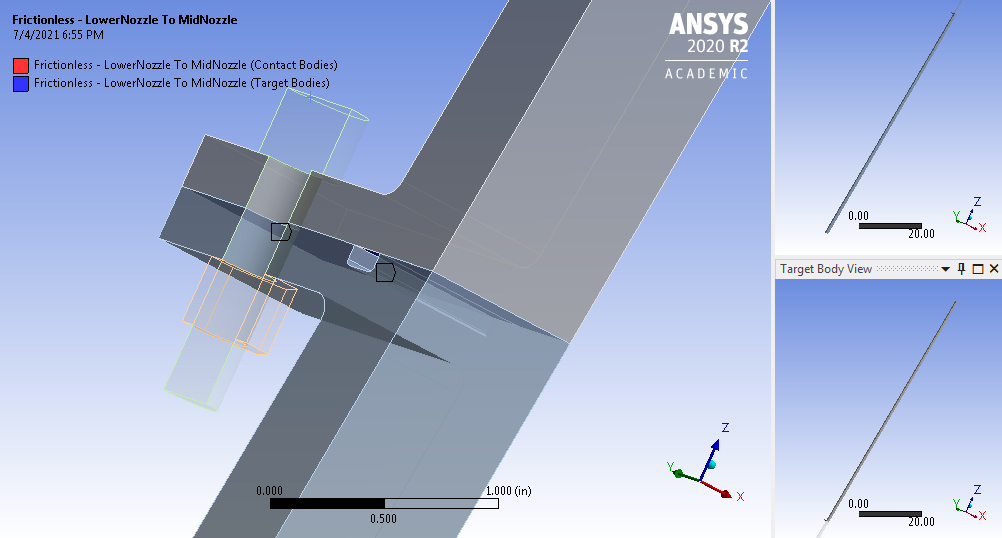 Lower to Middle Nozzle
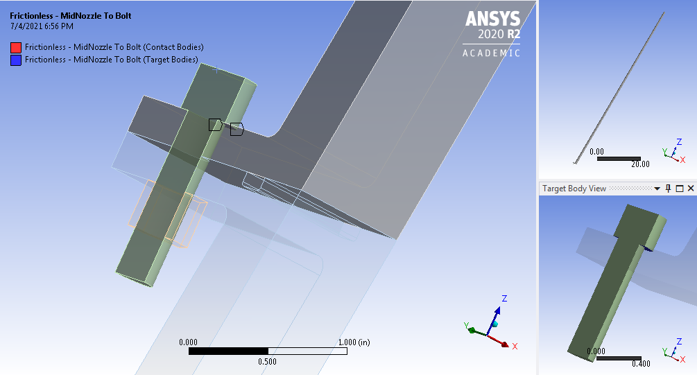 Middle Nozzle to Bolt
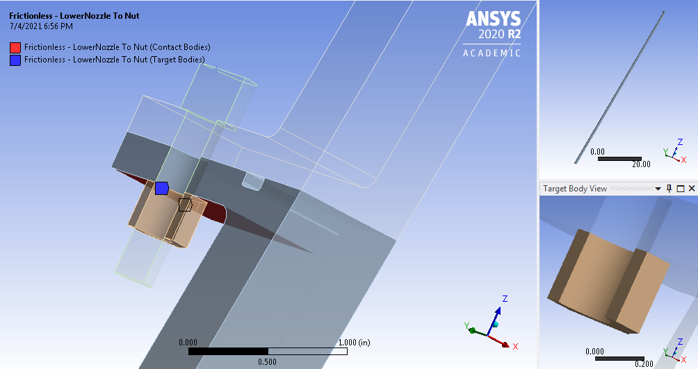 Lower Nozzle to Bolt
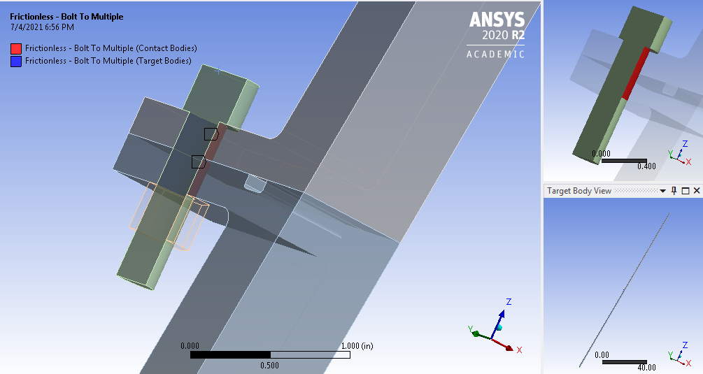 Bolt Contact
Finite Element Analysis Result
Force Convergence
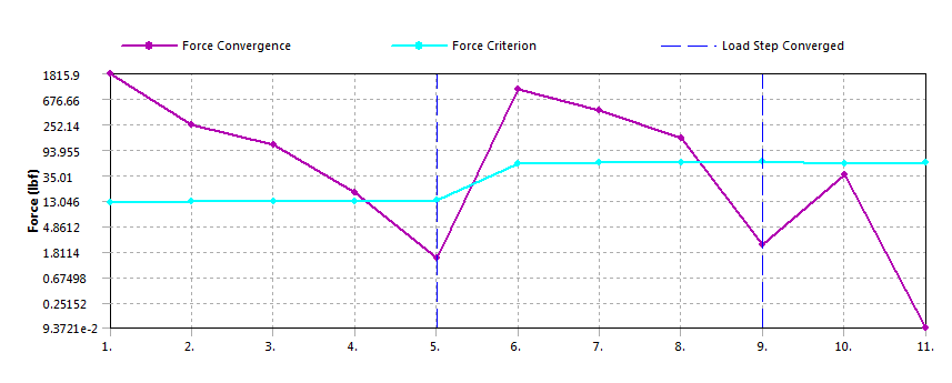 Force Convergence Result - Solution Converged After 11th Iterations
Total Deformation

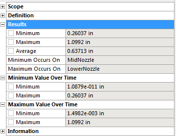
Minimum deformation occured at the fixed support of the middle nozzle, and maximum deformation of 1.0992 \(in\) happened at the lower nozzle. These results are inline with our initial calculation and prediction \eqref{thermal_strain}.
 Deformation Around the Bolted Nozzle Flanged
Hoop Stress

Normal Hoop Stress \(\sigma_{\theta}\) is around 1685 \(psi\) which is within ~1% range of our initial hoop stress calculation \eqref{hoop-stress}.
Equivalent Stress on Bolt

 Equivalent Stress on Bolt
Gap between Middle and Lower Nozzles
 Maximum and Minimum Gap Between Middle and Lower Nozzle