CFD & FEA Analysis of a 1.5 MW General Electric Wind Turbine (1.5xle)
15 May 2020Overview
This analysis covered the deformation due to aerodynamic loading of a wind turbine blade by performing a steady state one way fluid structure interaction (FSI). This analysis will use ANSYS Fluent to develop aerodynamic loading on the blade, the pressure loads on the blade, and the stresses and deformations that occurred on the blade.

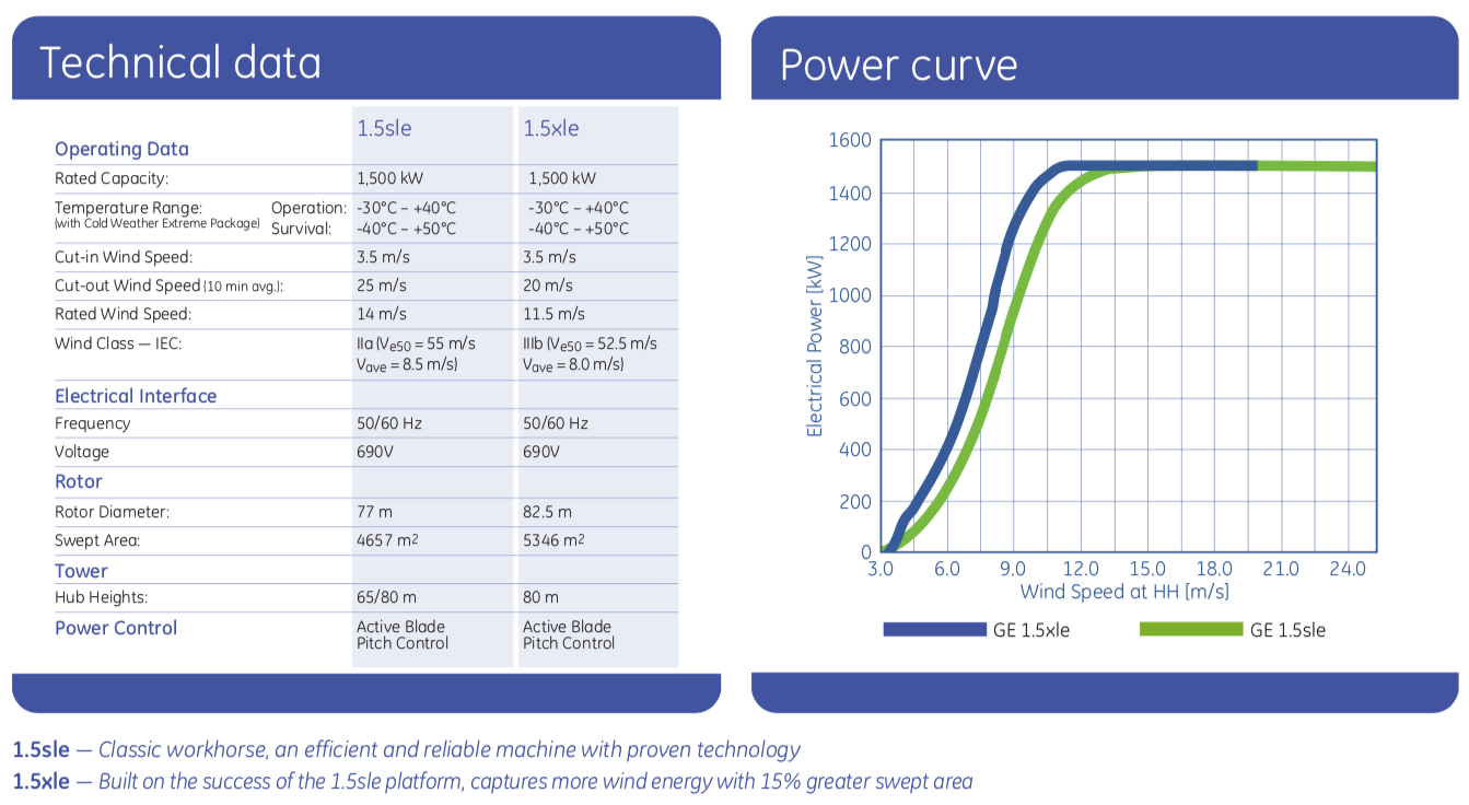 GE Wind Turbine Technical Data
Wind Turbine Blade Profile
The blade is 43.2 meters long and starts with a cylindrical shape at the root and then transitions to the airfoils S818, S825, and S826 for the root, body, and tip.
 Wind Turbine - Root View
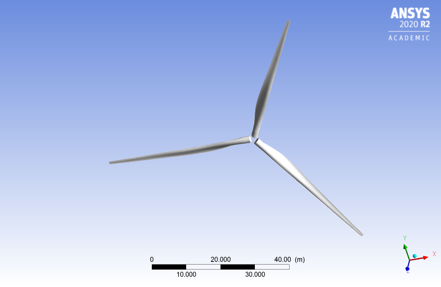 Wind Turbine - ISO View
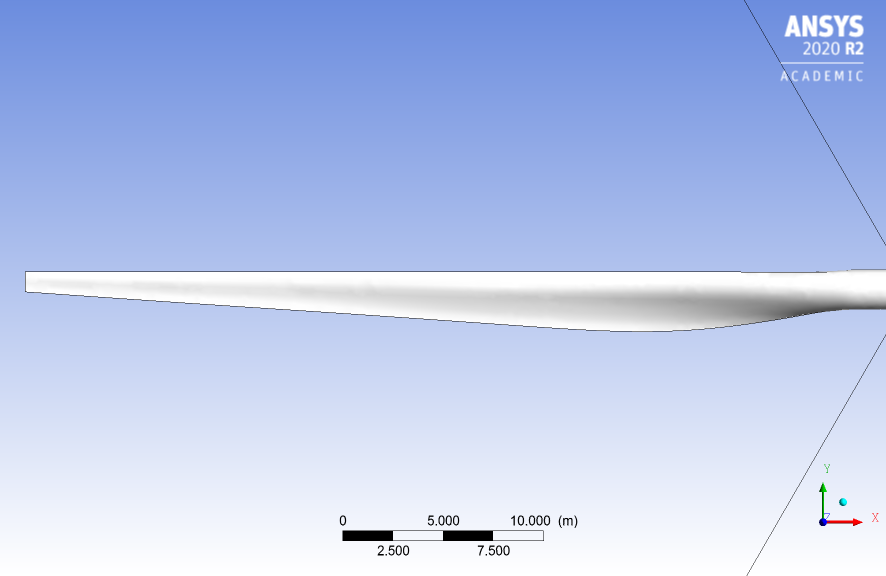 Wind Turbine - Front View
This blade also has pitch to vary as a function of radius, giving it a twist and the pitch angle at the blade tip is 4 degrees. The blade is made out of an orthotropic composite material, and it has varying thickness and spar inside of the blade for structural rigidity.
Case Setup
Governing equations are as follows (continuity and Navier-Stokes equations):
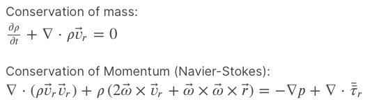 Governing Equations
Operating conditions is using air at standard conditions:
| Operating Conditions | Value |
|---|---|
| Air Temperature | 15 ℃ |
| Air Density | 1.225 kg/m^3 |
| Viscosity | 1.7894e-05 kg/(ms) |
| Fluid Domains | Boundary Conditions |
|---|---|
| Inlet | Velocity of 12 m/s with turbulent intensity of 5% and turbulent viscosity ratio of 10 |
| Outlet | Pressure of 1 atm |
| Blade | No-slip |
| Side Boundaries | Periodic |
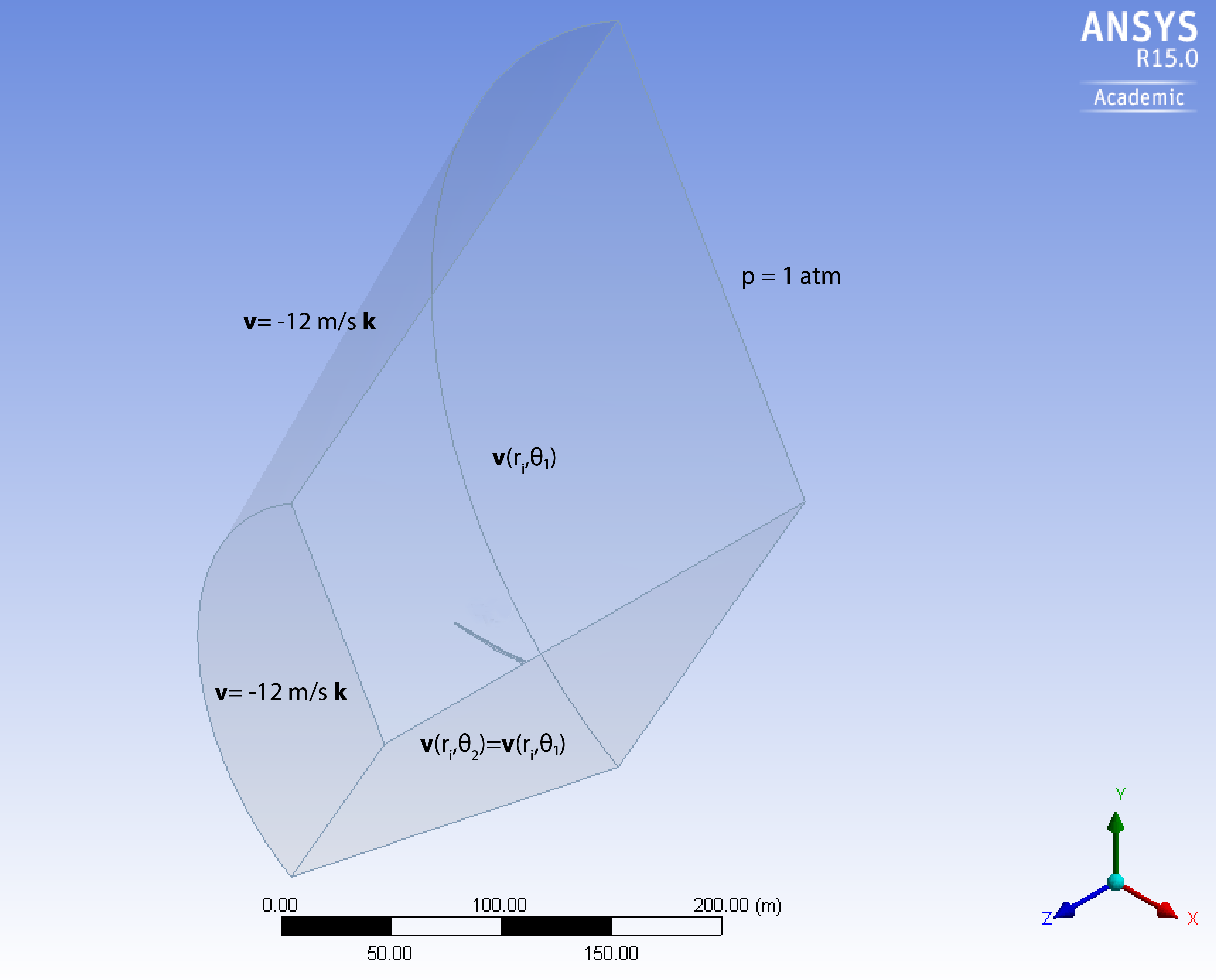 Fluid Domain Boundary Conditions
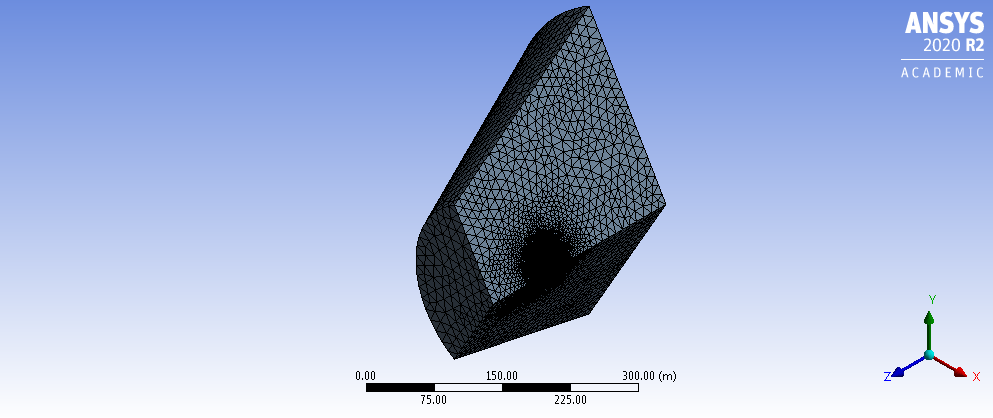 Fluid Domain Mesh
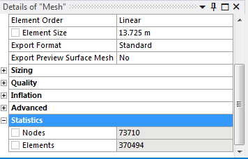 Fluid Domain Mesh Statistic
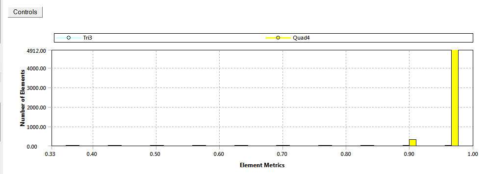
 Fluid Domain Mesh Orthogonality Metric
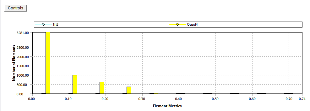
 Fluid Domain Mesh Skewness Metric
From the fluid domain mesh metrics, we have around 370,494 elements. So the total number of unknowns and the algebraic equations ANSYS Fluent needs to solve is around 2.22 million (u, v, w, p, k, 𝜔 - 6 unknowns from governing equations). The skewness and orthogonality quality of the mesh are also in acceptable range.
Skewness quality metrics
| Metrics | Value |
|---|---|
| Outstanding | 0-0.25 |
| Very Good | 0.25-0.50 |
| Good | 0.50-0.80 |
| Sufficient | 0.80-0.95 |
| Bad | 0.95-0.98 |
| Inappropriate | 0.98-1.00 |
Orthogonal quality metrics
| Metrics | Value |
|---|---|
| Inappropriate | 0-0.001 |
| Bad | 0.001-0.15 |
| Sufficient | 0.15-0.20 |
| Good | 0.20-0.70 |
| Very Good | 0.70-0.95 |
| Outstanding | 0.95-1.00 |
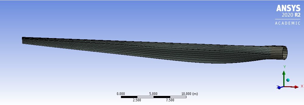 Wind Blade Structure Mesh
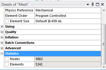 Wind Blade Structure Mesh - Statistic
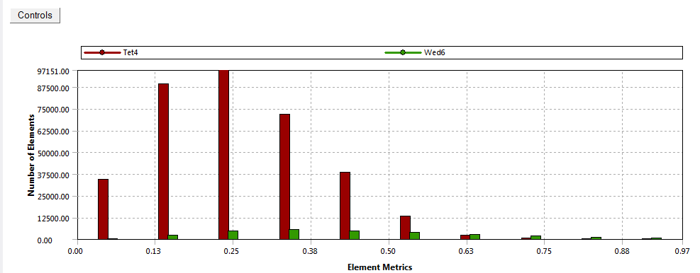
 Wind Blade Structure Mesh - Orthogonality Quality
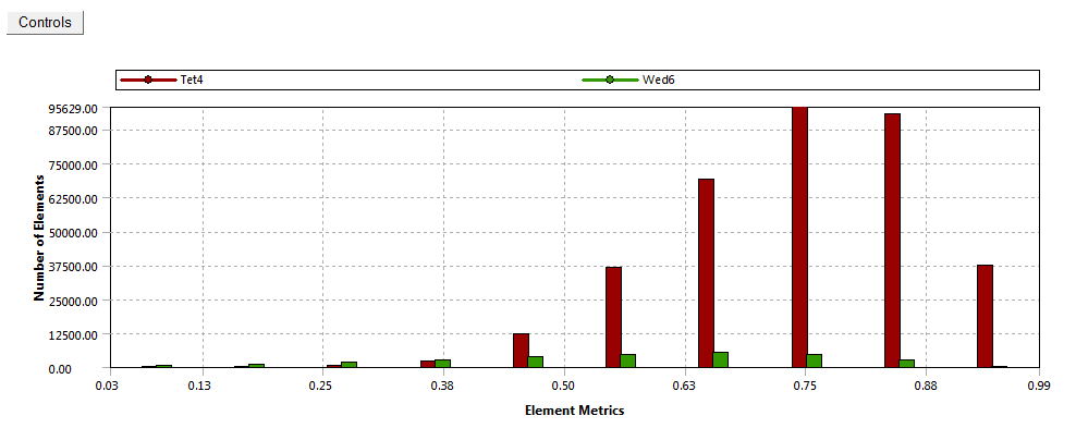
 Wind Blade Structure Mesh - Skewness Quality
Meshes quality for finite element analysis on the wind turbine blade are quite exceptional, where we have high orthogonality and low skewness. These will help the FEA solution to converge quickly with less iterations. The number of FEA unknowns that need to be solved by ANSYS Mechanical are 100 times lower when compared to the CFD analysis.
Computational Fluid Dynamics Result
| Mass Flow Rate | (kg/s) |
|---|---|
| inlet | 221216.84 |
| inlet-top | 664992.78 |
| outlet | -886209.81 |
| Net Mass Flow Rate | -0.1850242 |
Net mass flow rate is almost 0, and that’s one good indication that our model conserved its mass. The static pressure also has converged to a value between -7,000 to -8,000 Pa.
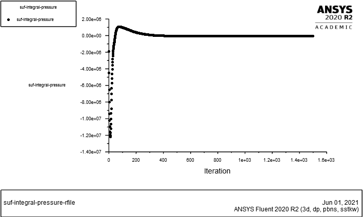 Surface Integral Static Pressure Convergence Plot
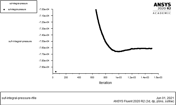 Zoom-in Plot
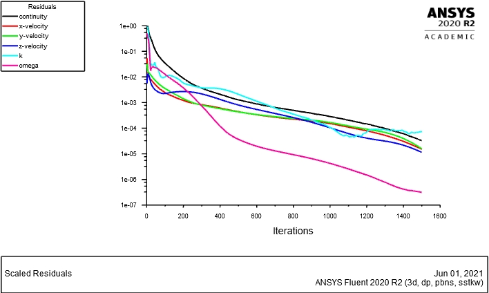 Residual Plot
From the residual plot, the results are converged after 1400 iterations when the residual for 𝜔 falls under the residual criteria (<1e-06 for this analysis). Higher iterations could be done to achieve more accurate result, but it’s not the priority for this analysis.
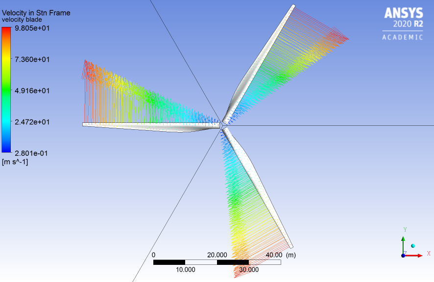 Local Blade Velocity
Local blade velocity increases with radius; the highest velocity recorded at the tip (98 m/s) and the lowest is near to the root of wind turbine blade (28 m/s).
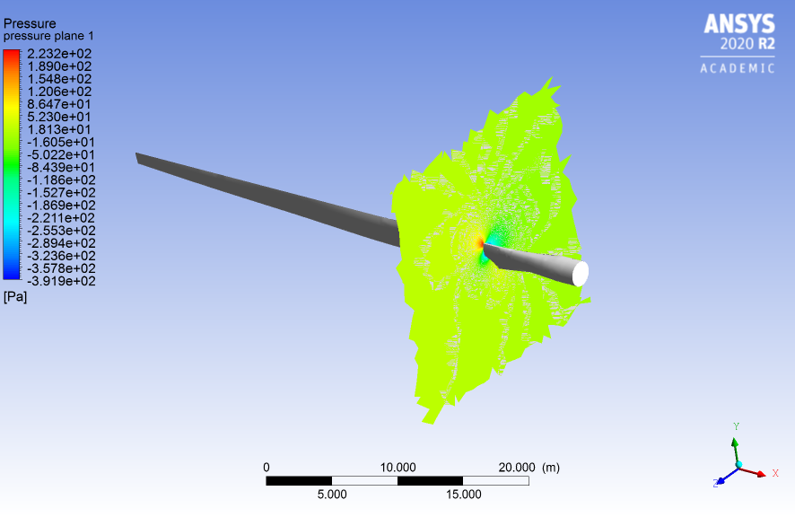
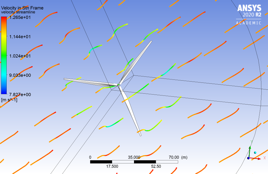 Velocity Streamlines Around The Wind Turbine
Wake effects are pronounced behind the the turbine (clear acceleration of the flow around the wake - gradient color change from blue to yellow/orange).
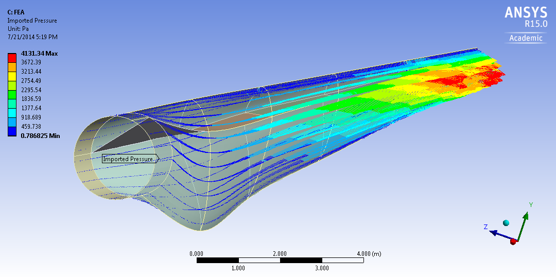
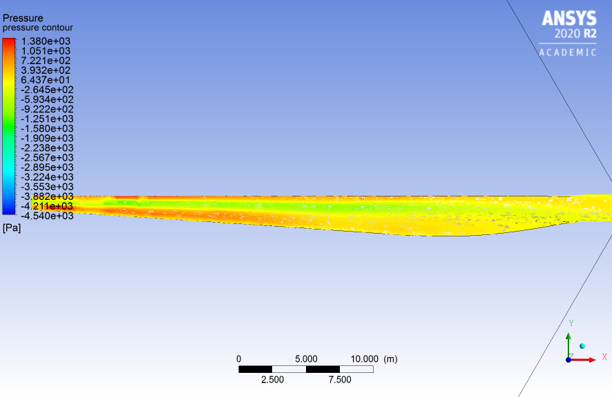 Wind Turbine Blade Front Surface - Pressure Contour
 Wind Turbine Blade Back Surface - Pressure Contour
The pressure is lower at the back surface of the blade compared to the front surface of the blade. The pressure difference between the front and back surface created a lift force that’ll in turn helps turning the blade around the z-axis.
 Y-Z Plane 10 Meters from root
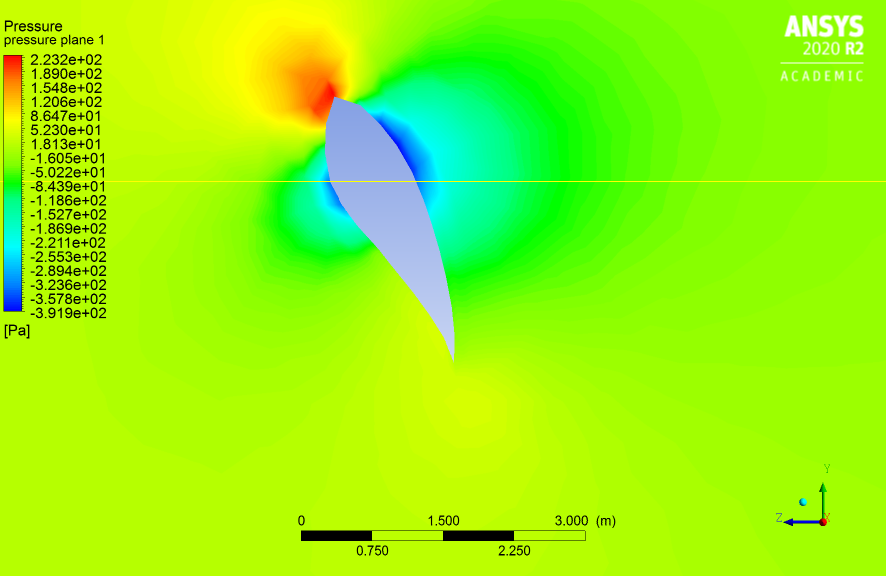 Y-Z Plane - Pressure Contour 10 Meters from root
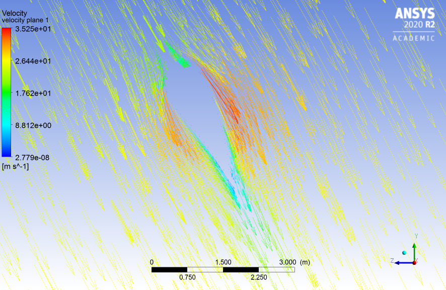 Y-Z Plane - Velocity Vector 10 Meters from root
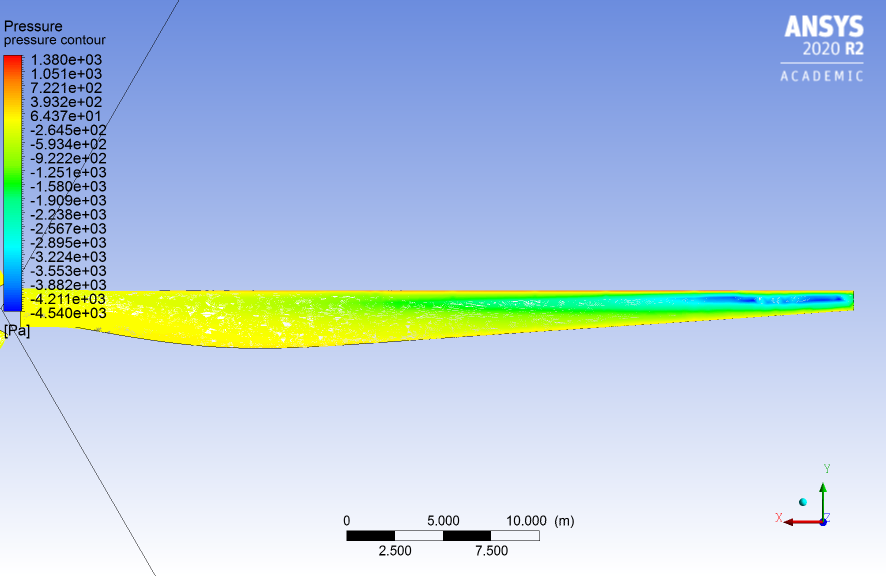
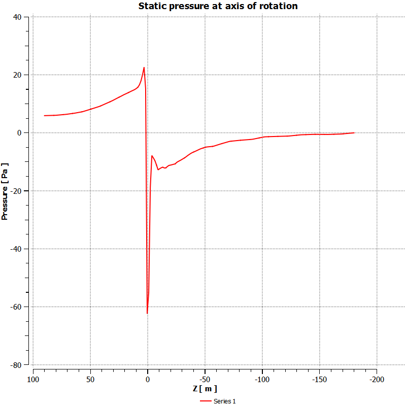 Static Pressure at Axis of Rotation (Z-Axis)
Wind Turbine Blade Structure
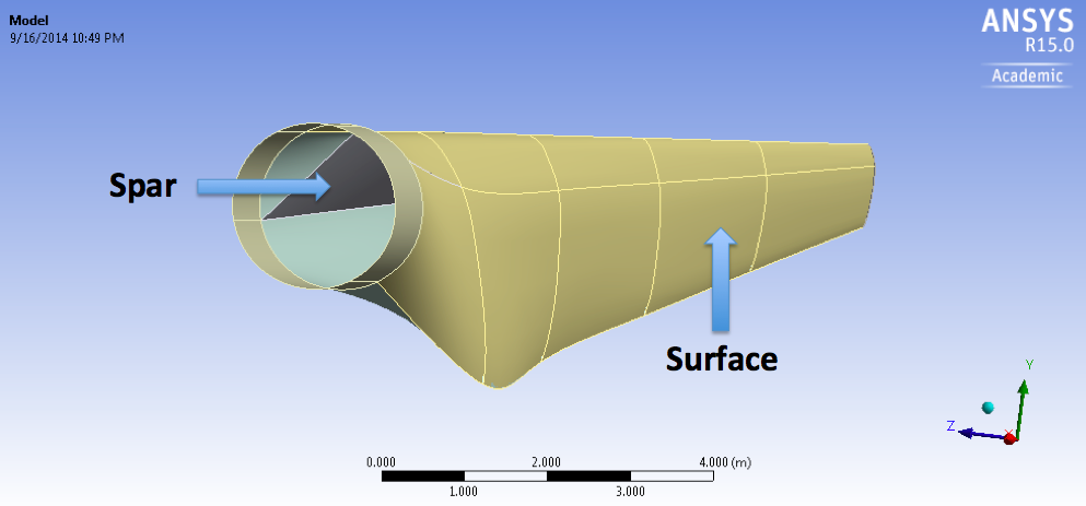 Wind Turbine Blade Outer Surface and Spar
The blade is composed of an outer surface and an inner spar. The thickness of the outside surface linearly decreases from 0.1 m at the root to 0.005 m at the tip. The spar has a similar thickness behavior with 0.1 m at its closest point to the root and 0.03 m at the tip.
Surface Profile
| X (m) | Thickness (m) |
|---|---|
| -1 | 0.1 |
| -44.2 | 0.005 |
Spar Profile
| X (m) | Thickness (m) |
|---|---|
| -3 | 0.1 |
| -44.2 | 0.03 |
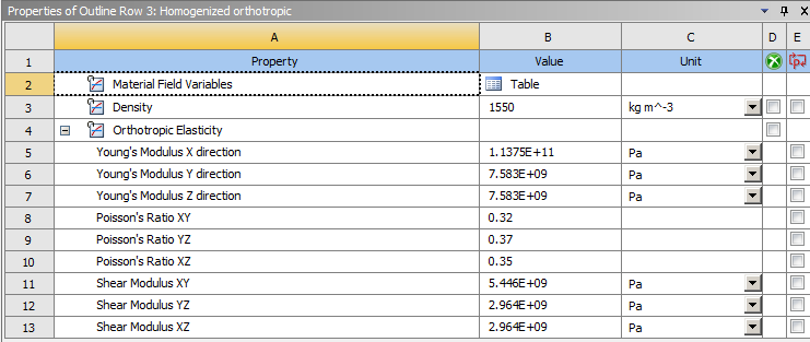 Material Properties
Wind turbine blades are now made of composite materials to reduce the weight of these massive machines. These values are representative of composite properties found in real wind turbine blades.
Finite Element Analysis (FEA) Result
Total deformation of wind turbine blade.
Maximum deformation occured at the tip of the wind turbin blade with magnitude of 38 cm, which correlate with the high pressure load at the wind blade tip during CFD analysis. Actual wind turbine do deform this way.
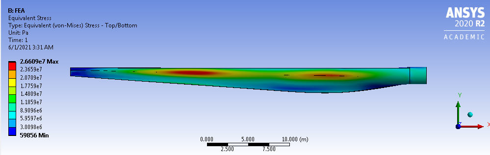 Equivalent Stress on Wind Turbine Blade - Front
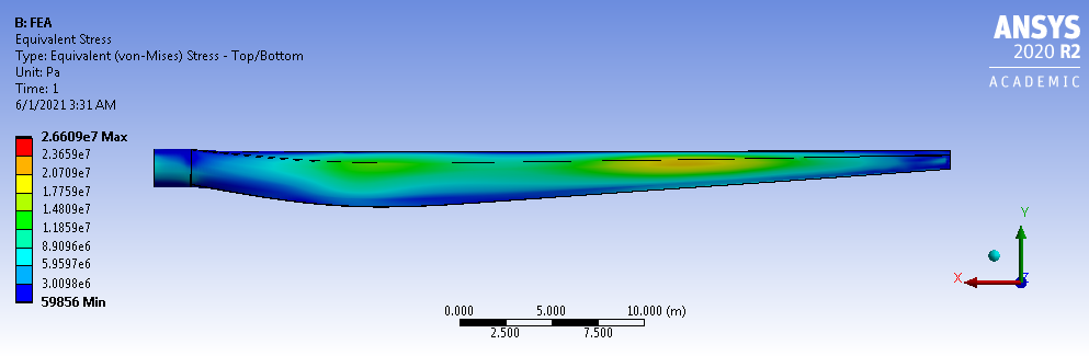 Equivalent Stress on Wind Turbine Blade - Back
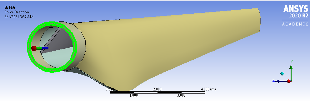 Force Reaction at the root
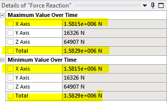 Force Reaction at the root - Result
Almost all of the force reaction is in the x-direction. This is caused by the centripetal acceleration acting on this blade.
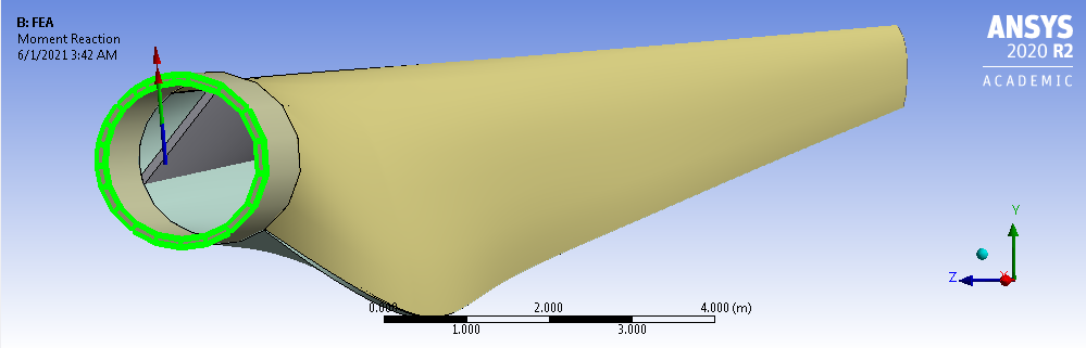 Moment Reaction at the root
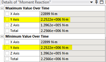 Moment Reaction at the root - Result