Rocker Bogie Robot — Building an autonomous search and rescue robot
18 Jun 2018Abstract
Collapse buildings and fires are a common risk faced by first responders in the world, and there are constant attempts to improve the safety and efficiency in search and rescue operations. This project aims to research and build an autonomous search and rescue vehicle capable of operating semi-autonomously in a one-story building under normal climatic conditions, assuming there is no fire as well. This system must also be able to be controlled manually if necessary. The search and rescue system must also be able to accurately identify people and animals, and relay its findings to its operators. To meet all the requirements detailed in this report, an unmanned ground vehicle (UGV) modeled as a rocker-bogie was designed. Using a combination of ultrasonic, infrared camera, regular camera and a LIDAR sensor, semi-autonomy would be achievable. The UGV will use a combination of a 2D map created with the LIDAR sensor, and odometry using wheel encoders to relay locations of victims to its operators. The infrared camera and regular camera would be used. The proposed design was made to be as inexpensive, versatile, and reliable as possible. The design chosen would be based of the rocker-bogie ground vehicle design and modified to meet the requirements of the challenge. This report details the design, project timeline, and management, work completed, and the proposed work to be completed.
Design Description
Concept
Before settling on the unmanned rocker bogie, the team brainstormed on multiple ideas to meet the requirements detailed in 3.1 of Senior Design Search and Rescue guidelines and requirements. These were generally ground based and aerial solutions for the search and rescue system. The three main concepts were a ground based tank like vehicle, a combination of a drone and a ground vehicle, a drone, and the rocker bogie concept. The systems using drones would use beacon based low-energy bluetooth local tracking systems to search the space, while the ground based vehicles utilized the LIDAR system to search. After consulting with the project advisor, the hybrid system (drone and ground vehicle) and drone system were dropped as they added a substantial degree of complexity, without a significant improvement in functionality in comparison to the ground based robots. Hence the ground based systems were chosen to be the likely solutions for the project. With further research the rocker bogie was chosen for its lightweight and versatile suspension system as compared to the tank like ground vehicle.
Concept Evaluation
To evaluate the options for the project, a decision matrix using points was used. The decision matrix compares a rocker bogie design, a drone using a beacon based local positioning system (LPS) and a combination of ground and air based systems to reach a decision on the optimal strategy for the project. As seen in the decision matrix titled “Decision Matrix” in the appendix, the best solution is the ground based rocker bogie, which beat out a combination of the rocker bogie and a drone, because of costs, and the unmanned aerial vehicle due to the added complexity of unmanned flight and maneuverability.
Sensor System Comparison
Decision matrix for sensors and CPU comparison.
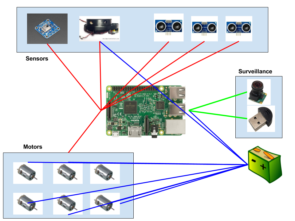 Sensors connection map
Detail Design
Chassis
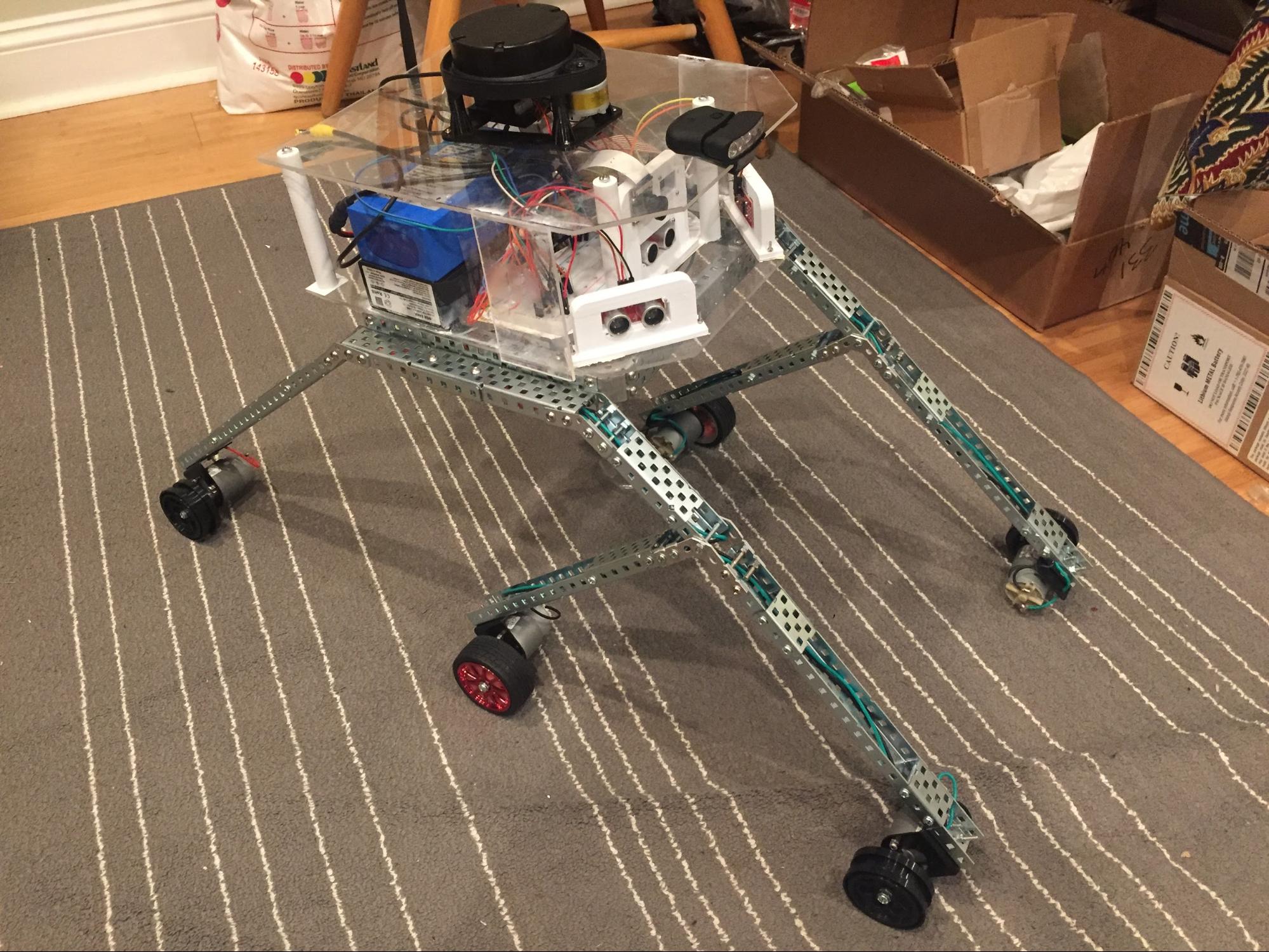
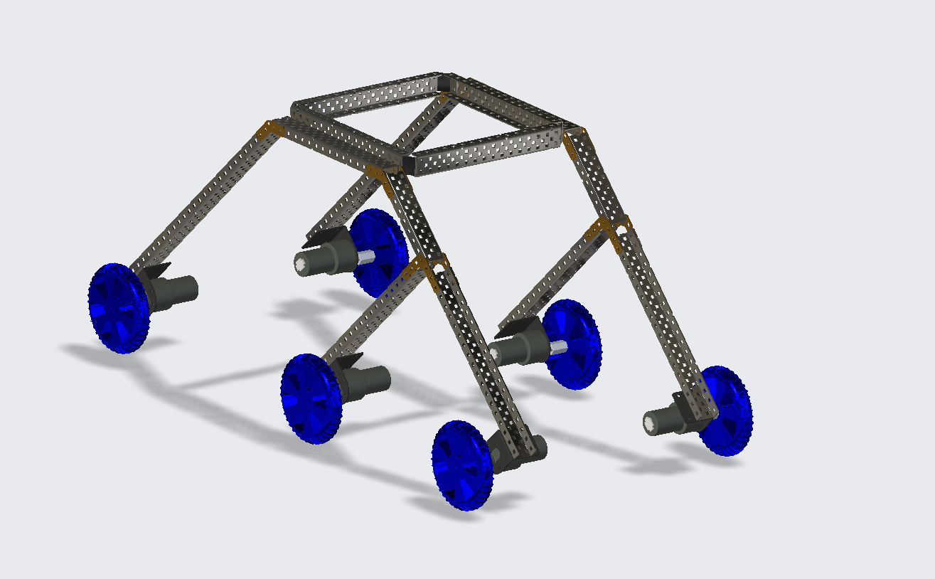 Isometric view of Rocker Bogie Robot
The chassis of this robot will use the rocker-bogie system as its structural build. The rocker-bogie suspension has become a proven mobility application known for its superior vehicle stability and obstacle-climbing capability. This mechanism allows climbing over high obstacles while keeping all six wheels in contact with the ground. In a rocker-bogie system, the left and right sides of the robot move independently. This allows the robot to transverse on uneven terrains which are possible in a collapsed building setting. The dimensions of this robot is designed to overcome the 1 feet obstacle that will be present in the obstacle. For the Winter term, the chassis was constructed using PVC Schedule 80 pipe materials. Mainly this material is used for pressure applications and has a thicker wall than schedule 40 pipes. This material is highly durable and easy to install compared to PVC and ABS Foam Core pipes. The weight of this material is 0.41 lb/ft. By calculating the total weight of all the structural parts of the robot, the estimated weight of this chassis is 4.305 lb. For the front chassis, it has two PVC pipes of length 10 inches each angled at 90 degrees. This length will provide a clearance of 14 inches for the front legs to go pass the obstacle.
As the team progress to the Spring term, flaws were present in using pipes as the chassis. The chassis fails to maintain structural symmetry as usage progresses. Taking comments from the faculty by the end of the winter term, the structure of the rocker bogie appears to be wobbly and not symmetrical. The rocker bogie is then constructed using C-Channel steels. Low cost is still maintained as steel is the most common and least expensive metal. The C-Channels are consumer off the shelf parts bought from VEX Robotics. The material is light and sturdy and has holes pre-drilled every 0.5” which allows for easy construction of the body and its components. The wheels have a diameter of 4” which is 3D-printed.
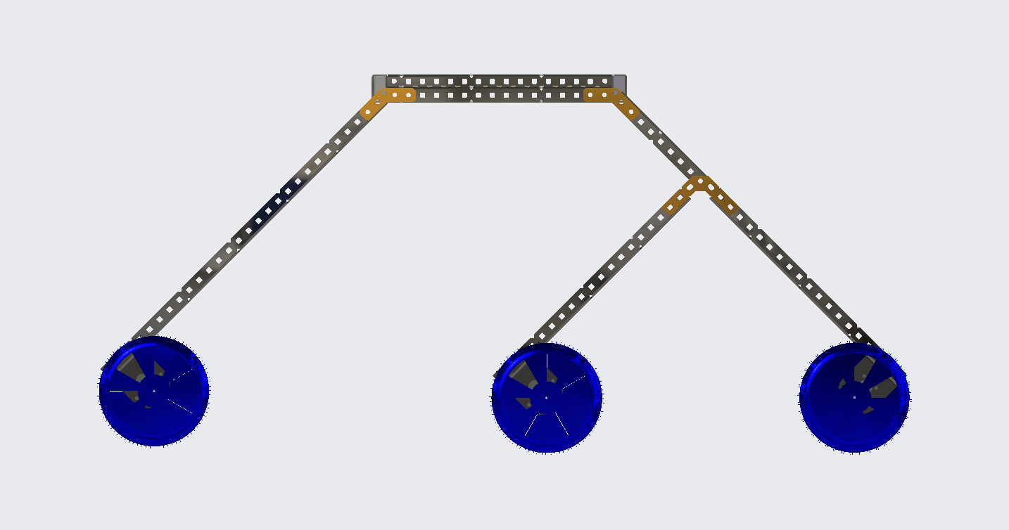 Side view of Rocker Bogie Robot
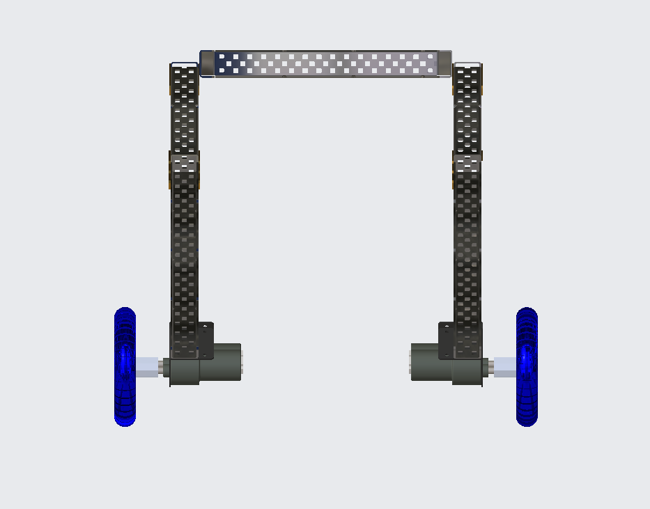 Front view of Rocker Bogie Robot
 Final assembly
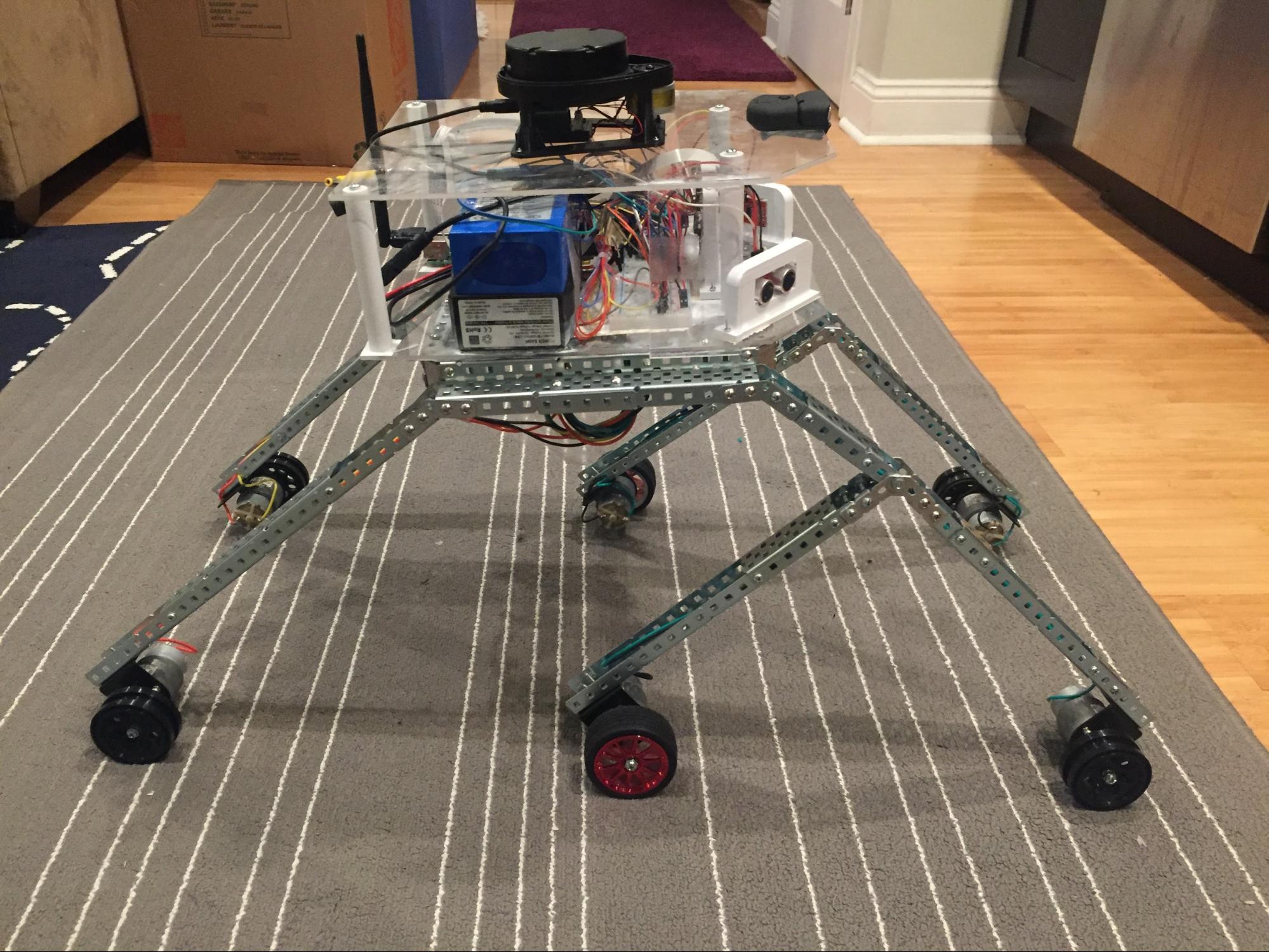 Final assembly - side view
Motor
The 6 legs of the rocker-bogie each have a 12V DC 30RPM Mini Gearbox Electric Motor. Each motor will produce a torque of roughly 0.88 ft-lb which should be more than capable of powering the 0.3 lbs, 4.92 in wide off-road tires connected to it. Considering that the motor has a stall torque of 1 ft-lb and 500mA this should be more than enough to guarantee smooth transportation of our vehicle and any added load. The effectiveness of the rocker-bogie comes from the design of the differential and as such each leg must be capable of moving independently, swiftly and powerfully. As a result the lightweight nature of the motor is very important and at 0.3625 lbs per motor our robot will not be burdened by the presence of 6 motors. In order to successfully hurdle obstacles, the two front and rear wheels will specifically have individual steering dc servomotors. In addition to hurdling obstacles, this will also grant the rocker-bogie the ability to swerve, curve and arch around obstacles. These obstacles will differ in sizes and so the shaft size of 6mm, couple with a relatively small diameter of 37 mm would mean that the motor would not interfere with the robots suspension system or risk coming into contact with an obstacle whilst hurdling objects.
Autonomous System Control
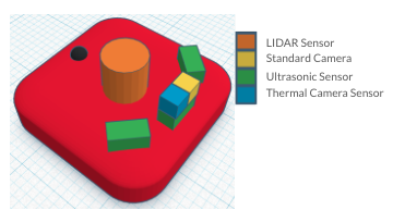
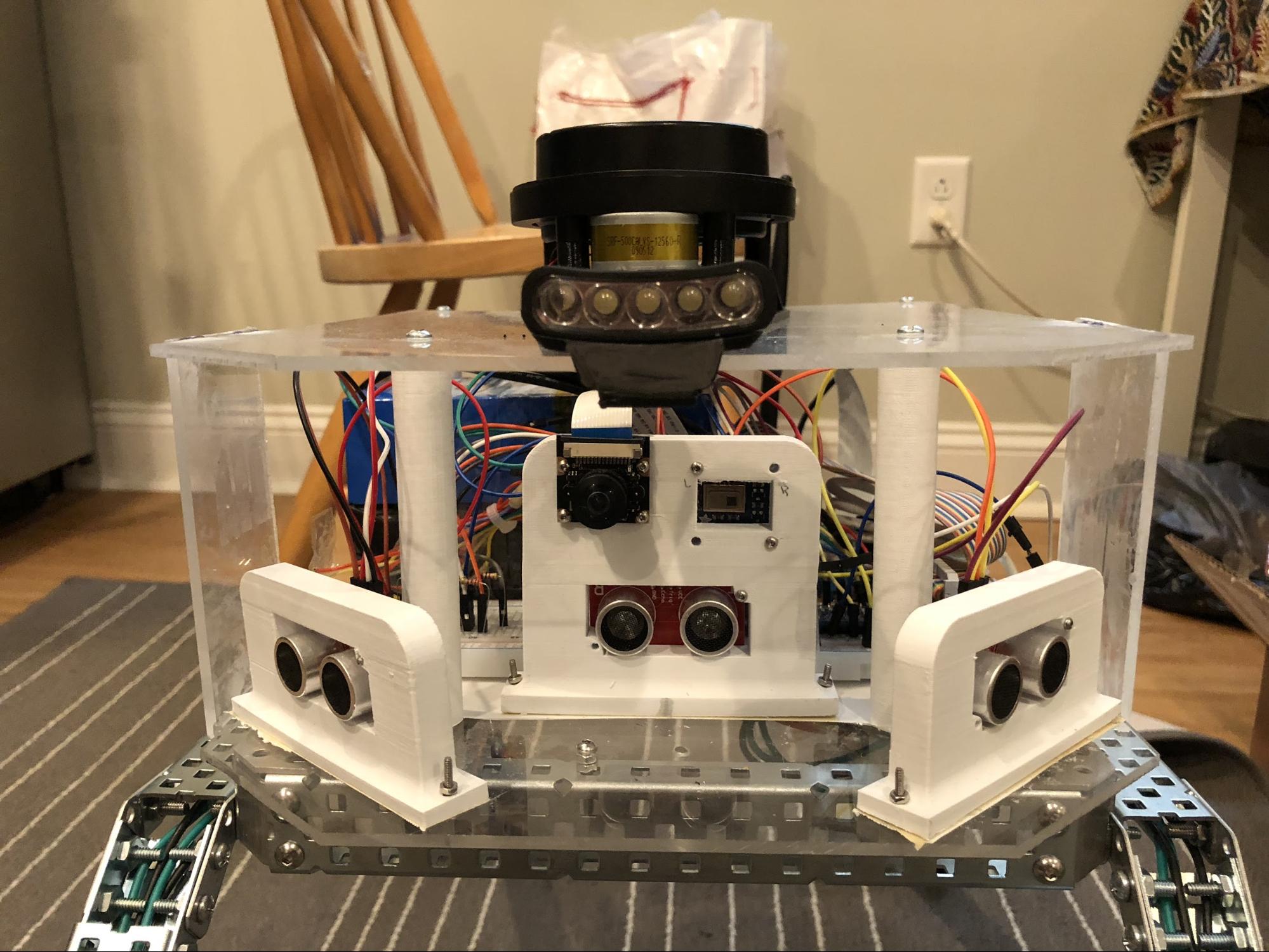 Sensor placement and assembly
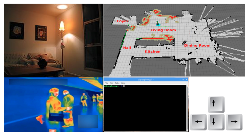
The robot was designed to run autonomously for two separate modes, the obstacle avoidance mode and the lifesign search mode. This will allow the rocker-bogie search and rescue robot to carry out mission task without the need for supervision. The operator of the robot will have the ability to activate the autonomous mode through remote connection available in the Raspberry Pi 3. In the autonomous mode, the robot will use a combination of 3 ultrasonic sensors, and LIDAR sensor to navigate the space and avoid obstacles. All the 3 ultrasonic sensors are mounted at the front of the robot where one sensor is in the center, and the remaining of sensors are mounted near the center ultrasonic sensor with 45° orientation. The advantages of the ultrasonic sensors setup are the ability to detect obstacle at wider range of view for the robot, and the data from each sensors can be used to calculate angle needed for the robot to avoid an obstacle. For example, when the robot is within 8 inches in front of an obstacle, the robot will stop and begin the process to avoid the obstacle. The data from each ultrasonic sensors will be used to compare and decide the movement direction of the robot. If the left ultrasonic sensor shows greater reading of the distance than the center and right ultrasonic sensors, the robot will move 45° to the left, and vice versa. The LIDAR sensor will allow the operator to see the 360° view of environment in real time as the robot navigate through the site.
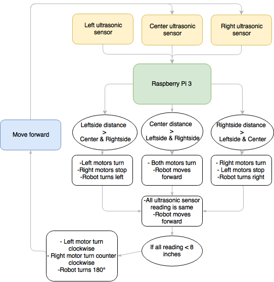 Basic obstacle avoidance logic
The lifesign search mode will utilize 1 thermal camera that is mounted in the same location as the front ultrasonic sensor. The thermal camera that is going to be used in this robot able to measure temperatures ranging from 0℃ to 80℃ (32℉ to 176℉). The capability of the thermal camera to measure such a huge range in temperature allows the robot to differentiate the source of heat from human body and the environment. The Raspberry Pi 3 used in this robot will produce a real time infrared video (8x8 pixels) in the remote desktop that will assists the operator to locate the victim. Since the thermal camera is in the same view as the front ultrasonic sensor, the robot will keep moving forward until the thermal camera read temperature near to the human body temperature in its field of view (37℃ or 98.6℉). Once the thermal camera have a human body temperature reading, the robot will align itself towards the source of heat to find the victim.
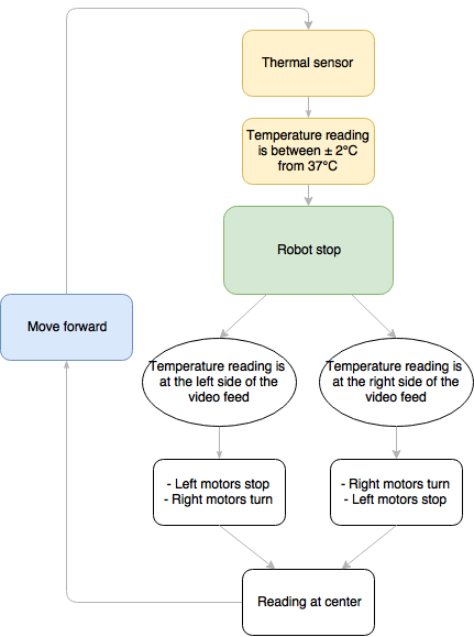 Lifesign search mode
Manual System Control
For the manual system control, a standard camera will also be mounted at the center along with the thermal camera and the front ultrasonic sensor. Type of camera that is going to be used is the Raspberry Pi Camera Module with a wide angle lens for better field of view. The operator of the robot will control the robot through wifi connection from a remote computer. A standard directional pad on the keyboard and GUI buttons will be used to control the robot’s movement. The operator will have the camera view, infrared video feed, simultaneous localization and mapping (SLAM) and sound output from microphone attached to the Raspberry Pi 3 to help locate the victims manually.
Environment Mapping System
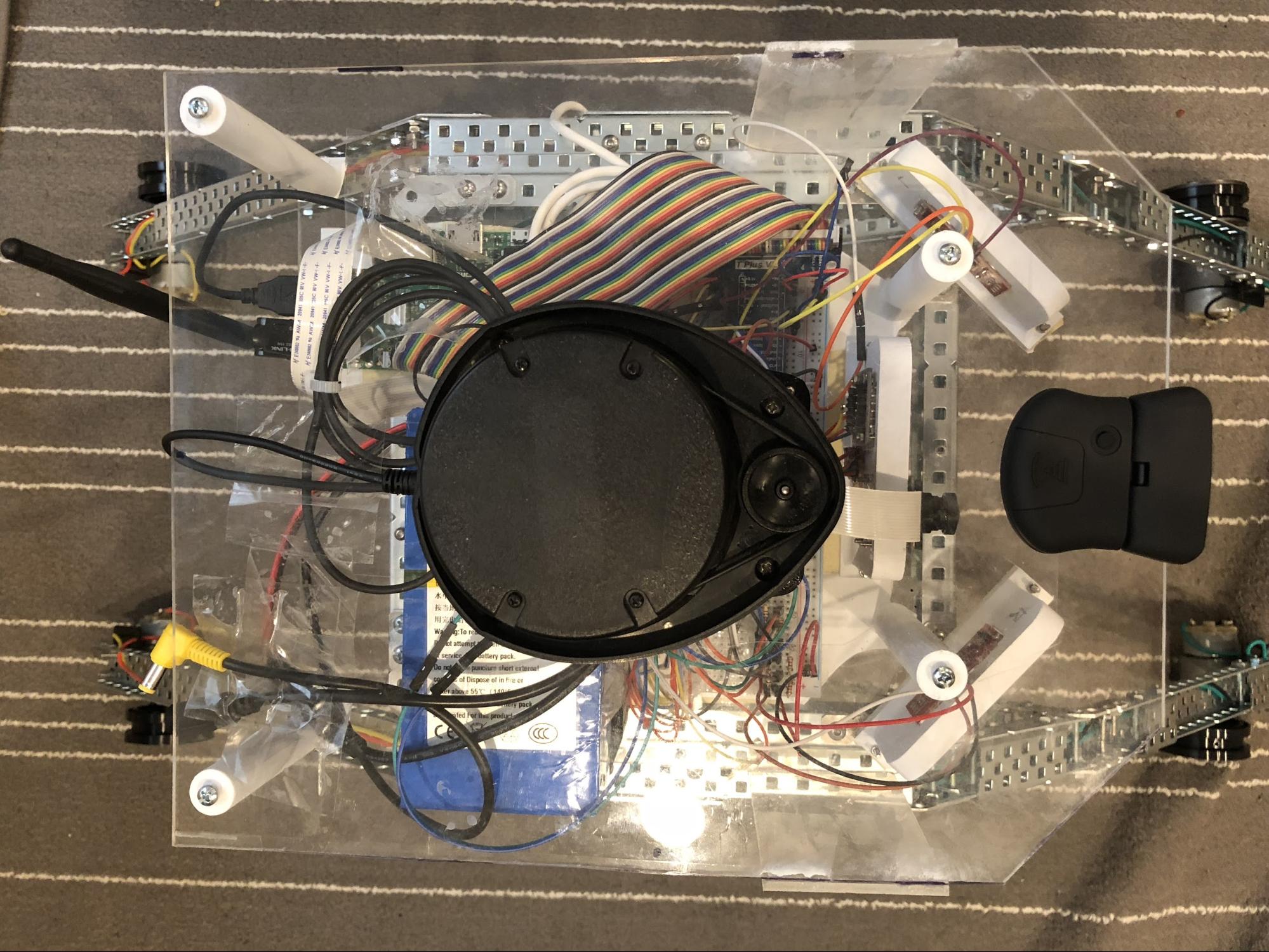
LIDAR sensor also serves another purpose in the rocker-bogie search and rescue system; which is to generate the map of the environment during the search and rescue process. To execute this idea, the team is going to utilize technique called simultaneous localization and mapping (SLAM). The LIDAR sensor used for the construction of the rocker-bogie robot system is salvaged from an old robotic vacuum; a Neato XV-11. The sensor is capable of recording 360° distance with interval of 4° for each measurement. The live data from the LIDAR sensor is then converted into a map with the help from an open source package for SLAM developed by Prof. Simon D. Levy from Washington & Lee University. Due to incompatibility of Robot Operating System (ROS) with the Raspbian Stretch OS on the Raspberry Pi 3, all programming for the environment mapping system has to be written in Python. The basis of SLAM process is by using laser scan to extract the current position of the robot at certain time. Whenever the robot moves, the odometry changes and the comparison between the previous laser scan data and the new one will determine the position and orientation of the robot in the workspace.
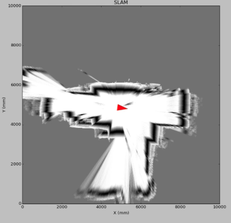 SLAM using onboard LIDAR sensor
Operator’s User Interface (OUI)
The user interface for the operator was designed entirely using Python to allow ease of use and to provide enough information for the operator to carry out search and rescue activity. The robot can be started easily by turning on the switch on the power source of the robot, then the operating system will boot up normally and all the necessary information will show up automatically on the operator’s device.
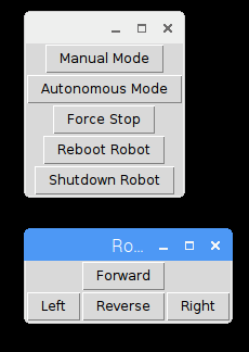 Available commands for the robot
The operator can easily switch between manual mode and autonomous mode using the OUI buttons. When the manual mode is activated, the robot can be controlled using keyboard by using “W,A,S,D” buttons to maneuver the robot or it can be controlled using the onscreen button. The SLAM, camera, and thermal view will be updated automatically at rate 1 ms to avoid cpu thermal throttle on the Raspberry Pi 3. Autonomous mode will utilize the ultrasonic sensors and the thermal sensor to execute the Obstacle Avoidance System and the Lifesign Search Mode. When the robot is in the autonomous mode, the operator can check for the status of the robot on the terminal display. The robot is equipped with 2 kill switches that will stop the robot activity and ensure the safety of the robot during the operation. 1 kill switch is located on the power source of the robot, and 1 remote kill switch is in the Operator’s User Interface (OUI).
Budget
For the project funding was provided by the Drexel Mechanical Engineering and Mechanics Department. The budget used so far for the project is only 29% from the total of USD 2,500 given. The amount used were for purchasing the structural parts , programmable parts and the parts pertaining to the motoring system. An estimate of the total cost of the project would be around a USD 1,000 at most. This projection is based on the fact that almost USD 2,000 was still available as of week 8. With week 8 being scheduled to be a period of assembly on our timeline. This meant that barring any unforeseen issues that may occur during testing all required parts had been purchased and delivered. Any more costs that may occur during the spring quarter would certainly be in the form of testing or perhaps replacement of a power source or some other easily replaceable component of our robot. The spending to date is summarized in the table “Project Budget” below.